A transformer failure report normally tells us what has already happened.
An FMEA should help us prevent what happens next.
That distinction is important.
The Central Electricity Authority’s July 2026 agenda of the Standing Committee on Substation Equipment Failure considers failures of 220 kV-and-above transformers and reactors occurring between January and June 2026. The agenda contains nine transformer events and one bus-reactor event.
The cases include inter-turn faults, bushing failures, high-energy internal arcing, OLTC failure, through-fault-related mechanical stresses, severe internal faults, busbar-flashover-associated damage and a reactor fire.
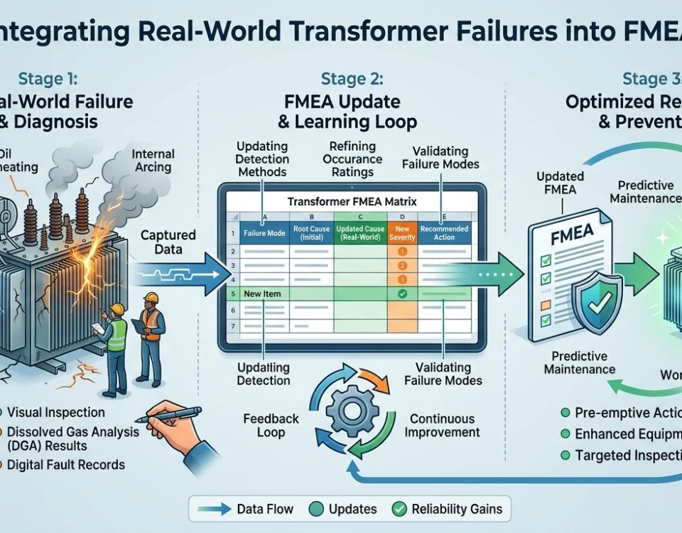
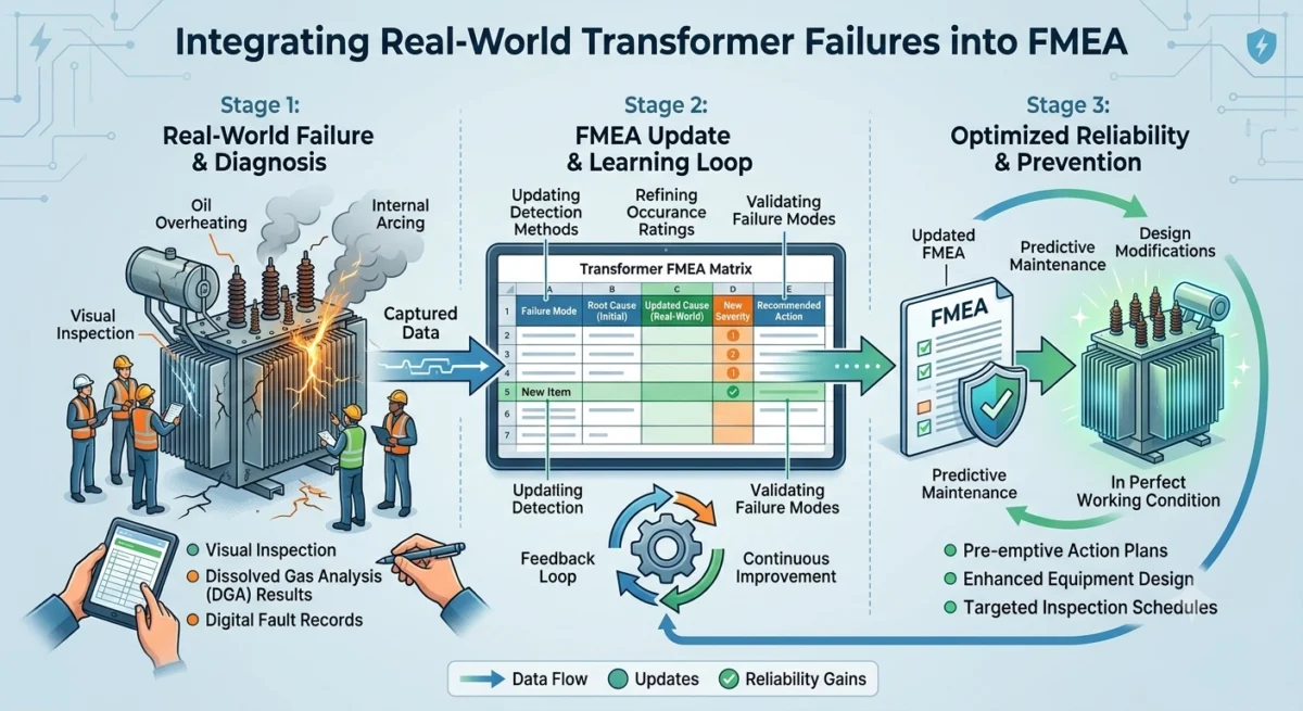
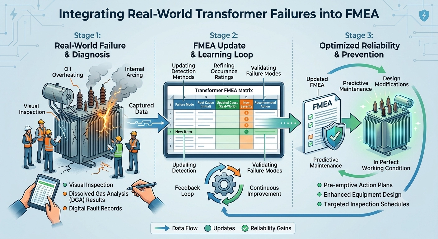
These should not remain only as investigation reports. They can become reusable FMEA knowledge.
An incident report and an FMEA answer different questions
An incident report generally asks: What happened?
A root-cause investigation asks: Why did it happen?
An effective FMEA should go one step further: Where else could the same mechanism occur, what would happen if it did, how would we detect the precursor, and what should we change before another failure occurs?
FMEA Executive is structured around this decomposition: an item or process step has functions, functions have requirements, requirements can fail through failure modes, and each failure mode can have multiple effects and causes. Action tracking and reuse of previous organisational problem-solving knowledge turn historical failures into a practical prevention library.
“Inter-turn fault” is not necessarily a root cause
Consider the 200 MVA Madakkathara transformer. The CEA case records differential and Buchholz operation and states the probable cause as winding inter-turn fault.
For FMEA purposes, I would classify the failure mode as inter-turn insulation breakdown. But the FMEA should not stop there.
Why did turn-to-turn insulation fail? Possibilities may include thermal ageing, local overheating, moisture, contamination, winding displacement following fault stresses, transient electrical stress or a manufacturing defect.
These are hypotheses until evidence discriminates among them.
Do not put the failure mode back into the FMEA as though it were automatically the root cause.
Panyor shows what a useful failure mechanism looks like
The Panyor incident is more instructive. Diagnostic testing indicated unhealthy tertiary bushings and high-energy internal arcing. The report associates the failure with aged bushings and discusses deterioration of insulation, possible moisture absorption and partial discharge.
This allows a much more useful FMEA chain:
- Bushing ageing / moisture uptake
- Dielectric deterioration
- Partial discharge
- Flashover / high-energy arc
- Bushing rupture and oil release
- Transformer bank trip
- Potential fire and loss of system capacity
Now the controls become obvious. Instead of merely asking whether annual maintenance was completed, the organisation can monitor tan delta trends, capacitance changes, PD behaviour, moisture indicators, DGA and age/design population. The FMEA has moved from documentation to prevention.
New Pirana may contain one of the most valuable clues in the report
The 315 MVA New Pirana transformer failed while feeding a through-fault. The report states severe mechanical stress as the probable cause and records an especially important fact: 21 through-faults had occurred since 1 March 2025 before the final event.
This immediately suggests a different reliability model.
Perhaps the relevant variable is not: Has the transformer passed maintenance? – Yes/No but: How much cumulative short-circuit mechanical stress has this transformer absorbed?
An FMEA can therefore create a new potential cause: Cumulative electrodynamic degradation due to repeated through-fault exposure.
And a new preventive action: Create a transformer through-fault exposure counter.
But even counting events may be insufficient. A 5 kA fault lasting 100 ms is not equivalent to a 30 kA fault lasting 500 ms. The reliability database should eventually consider magnitude, duration, asymmetry and transformer design withstand capability.
The Lapanga case demonstrates the importance of weak signals
The Lapanga transformer underwent previous condition monitoring. Most results were reported in order, although the 220 kV B-phase bushing had noteworthy tan-delta measurements before the later catastrophic event.
The lesson should not automatically be: The tan-delta caused the failure. That would be hindsight bias.
The better question is: What decision rule should an FMEA use when a measurement moves away from normal but has not yet crossed a conventional alarm boundary?
This is where a living FMEA should connect condition-monitoring data to actions. A weak signal should have an owner, a threshold, a review date, a hypothesis, and a closure criterion.
Otherwise condition monitoring can become an excellent system for recording deterioration without preventing failure.
Through-fault should not simply be entered as ’cause’
The Vijayawada, New Pirana and Ataur cases illustrate another important FMEA distinction.
A network fault is frequently the stress event. The transformer failure mechanism may instead be winding movement, conductor displacement, clamping weakness, bushing mechanical failure, insulation damage, lead movement or cumulative electrodynamic fatigue.
If the FMEA says ‘Cause: Through-fault’, the organisation has limited ability to act.
But if it says ‘Cause: accumulated electrodynamic forces exceeding residual mechanical restraint capability after repeated through-fault exposure’, the possible controls become much clearer: SFRA, impedance comparison, winding resistance, mechanical inspection, fault-duty recording, design verification and event-triggered engineering review.
CEA itself recommends SFRA following through-faults, bushing capacitance/tan-delta and DGA health assessment, condition monitoring and residual-life assessment for ageing transformers.
Not every probable cause deserves the same confidence
The Bikaner reactor suffered a severe blast and fire. The report states an internal fault, but all bushings were badly damaged and post-failure testing could not be performed; the unit was completely burnt.
An FMEA knowledge database should therefore distinguish causal confidence:
- Confirmed
- Highly probable
- Probable
- Possible
- Unknown
This apparently simple field protects future engineers from a dangerous cognitive error. Once a hypothesis is entered into an official database, people may later treat it as fact. A reliability database therefore needs to preserve uncertainty, not erase it.
Kahneman and Tversky: avoid learning the wrong lesson from failures
Once we know a transformer failed, hindsight can make the preceding events look obvious.
An abnormal reading suddenly appears predictive. An old bushing suddenly appears obviously too old. A through-fault suddenly becomes the inevitable explanation.
The reliability engineer should ask: Would I have considered this signal important if I did not already know the transformer eventually failed?
And: How frequently does the same signal appear in transformers that continue operating normally?
Without that comparison, we risk converting memorable stories into false rules.
Popper: every FMEA cause should contain the possibility of being wrong
Karl Popper gives us an equally useful test.
Suppose we enter: Cause – repeated through-faults progressively weaken transformer winding support.
The next question should be: What evidence would falsify this?
If hundreds of comparable transformers withstand equal or greater through-fault duty without measurable deformation or higher failure rates, our hypothesis becomes weaker.
That is good. A useful FMEA is not a collection of unquestionable statements. It is a collection of testable risk hypotheses that improves as evidence accumulates.
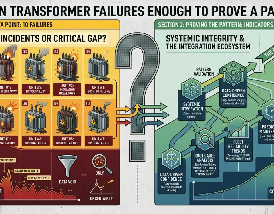
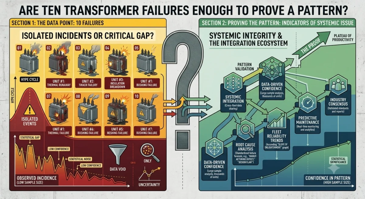
From ten failures to one knowledge system
The ten CEA cases should therefore not become ten disconnected FMEAs. They should populate common failure families:
- Dielectric insulation failure
- Bushing failure
- Through-fault / mechanical withstand failure
- OLTC failure
- Internal high-energy fault
- External grid-initiated equipment damage
- Fire and containment failure
The next time any transformer exhibits rising acetylene, unusual bushing tan delta, a significant through-fault, abnormal SFRA or unusual OLTC behaviour, the database should retrieve the historical cases immediately.
A living FMEA changes the question
A static FMEA asks: Did we complete the FMEA?
A living FMEA asks: What has changed in our evidence since the last review? A transformer failed. The FMEA changes.
A healthy transformer survives its twentieth through-fault. The FMEA should change again.
A new bushing design demonstrates dramatically lower ageing behaviour. The occurrence assumptions should change.
A diagnostic technology begins detecting defects months earlier. The detection rating should change. In other words, the document is never really finished.
Conclusion
The CEA failure reports contain something more valuable than ten unfortunate equipment failures. They contain the beginnings of a transformer failure knowledge graph.
Failure modes connect to effects. Effects connect to consequences. Mechanisms connect to potential causes. Causes connect to weak signals. Weak signals connect to controls. Controls connect to responsible people and actions.
And each new incident either strengthens or weakens what we previously believed. That is where FMEA becomes much more than a compliance document.
FMEA should become a living, ownership-driven reliability system that continuously absorbs operating evidence, challenges its previous assumptions, identifies emerging failure modes, connects risks across equipment and grid interfaces, and triggers preventive action before the next costly or catastrophic failure occurs.
Source note
Based on the Central Electricity Authority, Ministry of Power, Standing Committee on Substation Equipment Failure agenda dated 25 July 2026, covering reported 220 kV-and-above transformer and reactor failures during January-June 2026.